
Cat 6 Wiring Diagram: Complete Guide to Cat 6 Cable Pinout
You’re running ethernet through your house and you’ve got a bag of Cat 6 cable, a punch-down tool, and a pile of wall plates, and suddenly you realize you aren’t sure exactly which wire goes where. The cat 6 wiring diagram you need isn’t complicated, but getting it wrong means a connection that doesn’t work or works unreliably at 100Mbps when you were expecting gigabit speeds. Getting it right the first time saves a lot of troubleshooting later.
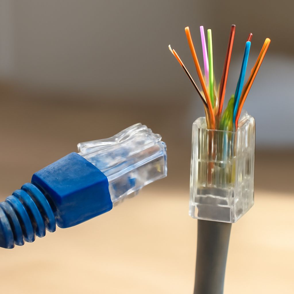
A cat 6 cable diagram follows one of two wiring standards: T568A or T568B. The cat 6 diagram itself shows eight colored wires arranged in four pairs, each pair twisted tightly together to reduce interference. Understanding the cat 6 pinout tells you exactly which wire goes to which pin in your keystone jack, patch panel, or RJ45 plug. A cat 6 wiring diagram for wall plates is the same standard, just applied to a different physical component.
Understanding the Cat 6 Color Code
Cat 6 cable contains four twisted pairs: orange/orange-white, green/green-white, blue/blue-white, and brown/brown-white. The twisting of each pair is what gives the cable its interference rejection properties. Never untwist more than half an inch of each pair when terminating, as excess untwisting degrades performance at high speeds.
The two wiring standards, T568A and T568B, arrange these same eight wires in different pin orders. T568B is more common in commercial installations in North America. T568A is used in some government installations and is technically specified in some structured cabling standards. Either standard works; what matters is consistency throughout your installation. Do not mix T568A at one end and T568B at the other end of the same cable run unless you intentionally want a crossover cable.
The T568B Cat 6 Pinout
This is the most common wiring configuration for a cat 6 cable diagram in residential and small commercial installations. Reading pins 1 through 8 from left to right with the clip facing down:
- Pin 1: Orange-white
- Pin 2: Orange
- Pin 3: Green-white
- Pin 4: Blue
- Pin 5: Blue-white
- Pin 6: Green
- Pin 7: Brown-white
- Pin 8: Brown
Apply this same cat 6 pinout at both ends of the cable run for a straight-through connection, which is what you need to connect a computer to a switch or a wall plate to a patch panel.
The T568A Cat 6 Wiring Diagram
T568A swaps the orange pair with the green pair compared to T568B. Reading pins 1 through 8:
- Pin 1: Green-white
- Pin 2: Green
- Pin 3: Orange-white
- Pin 4: Blue
- Pin 5: Blue-white
- Pin 6: Orange
- Pin 7: Brown-white
- Pin 8: Brown
Again, consistency is the rule. Whatever cat 6 diagram standard you choose, use it end to end throughout your installation.
Wiring Cat 6 Wall Plates
A cat 6 wiring diagram for wall plates applies the same T568A or T568B pinout to a keystone jack rather than a modular plug. The keystone jack has labeled slots marked with both color standards, usually printed in two colors (one for T568A, one for T568B). Push each wire into the labeled slot for your chosen standard using a punch-down tool, then snap the keystone into the wall plate faceplate.
Strip only the outer jacket, not the individual wire insulation. The punch-down tool pierces the insulation and makes contact with the conductor as it seats the wire. Trim excess wire length after punching down. A clean termination with minimal untwisting and no excess wire hanging out of the jack is the goal.
Next steps: After wiring both ends of your runs, test each cable with a basic ethernet cable tester before closing up the walls or securing the faceplates. These testers cost around fifteen to twenty dollars and verify that all eight pins are correctly connected and that no pair is mis-wired or open. Catching a wiring error before the drywall goes back up is worth far more than the cost of the tester.